Discussion and overview of engine port design
The most efficient shape for maximum airflow is simply a straight, constant diameter pipe. Therefore, the ideal shape for an intake port would be one with no bends. Due to constraints by the size and shape of the engine, that is not a possibility. However, maximizing airflow through the engine head can still improve engine performance. This is done by adjusting the shape of the valve seats, as well as the intake and exhaust ports to achieve the maximum airflow and reduce separation which occurs when the airflow is forced to undergo a rapid change in direction. The goal is to be as smooth as possible when changing directions. The short side radius of the intake port is imperative to decreasing the separation that occurs in the airflow.
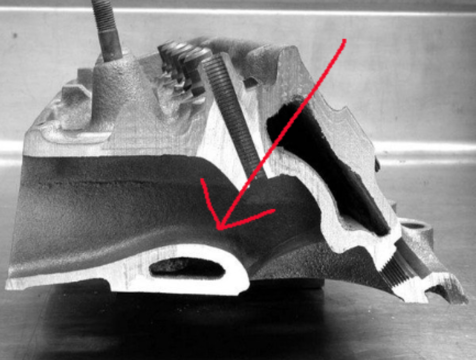
Photo thanks to chevydiy.com
If it is not gently shaped, there will be a significant amount of separation, resulting in internal drag and decreasing the amount of airflow that will make it to the port. At P2P, we adjust the valve seats to have five angles.
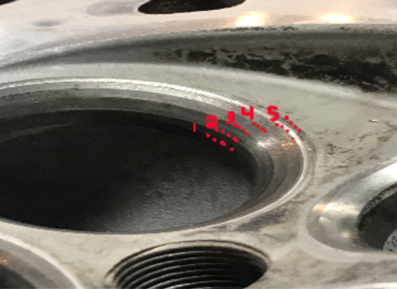
The angles are critical to help airflow into the combustion chamber, as well as making the valve sealing efficient. A properly angled valve seat also increases the life of the valve and the valve guide.
The amount of airflow an engine needs in cubic feet per minute (cfm) is largely based on the swept volume of the engine which is the displacement of the engine through two full rotations of the crankshaft in cubic inches displacement of the engine (CID), the volumetric efficiency (VE), and the rpm.
- The cfm is found by converting the CID to cubic feet, and since the engine is undergoing two revolutions in this time, half of the rpm needed for peak power is used. The VE as a decimal is multiplied by the result to get the required cfm.
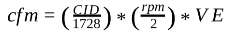
- This value can be converted to maximum horsepower (hp) by dividing the found value by the cfm/hp of the engine. An efficient four-stroke cycle piston engine would have about 1.4 cfm/hp value, but at high rpm it is better to have an excess of airflow through the engine.
Cylinder Head Characteristics
- Exhaust to Intake ratio: The ratio of the airflow tends to be about 60-75%. In cases where the exhaust flow is even closer to the intake flow, it is often an indication that the intake port is not developed well. At ratios higher than 85%, special camshafts are required to slow down the flow on the exhaust side. Otherwise, there is unused air and fuel leaving the engine that could have been used more efficiently to make more power.
The minimum area for an inlet of an intake runner can be found with the following equation.
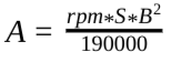 Where S is the stroke in inches, and B is the bore diameter in inches. The ideal length of
the intake runner has many equations that result in similar numbers for the same cylinder head.
A good guide for deciding on the length is
Where S is the stroke in inches, and B is the bore diameter in inches. The ideal length of
the intake runner has many equations that result in similar numbers for the same cylinder head.
A good guide for deciding on the length is
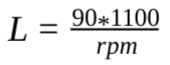 . While
none of the equations are perfect, using any is more helpful than simply guessing.
. While
none of the equations are perfect, using any is more helpful than simply guessing.
The ideal length of the exhaust port is often assumed to be of equal length with the intake, but
that is not always the case. The length of the exhaust port beginning from the valve seat can be
found with: 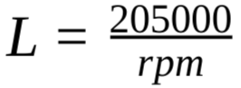 .
.
Flow Bench Testing
The airflow in cfm through a cylinder head can be analyzed using a flow bench to get an idea of how well the ports flow air. The testing is done with the valves lifted 5% of the valve diameter. The tests also use accommodations to simulate intake and exhaust pipes as well as a cylinder bore adapter to simulate being attached to the engine. A spark plug is also inserted into the cylinder head to achieve accurate results.
The flow bench provides results in terms of cfm with the inputs of test pressure, temperature, and the local barometric pressure. The resulting cfm can be used to predict the engine horsepower using the following equation.
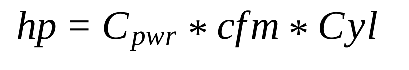
In the equation, Cpwr is a coefficient that has been derived empirically that changes based on the test pressure, and Cyl is simply the number of cylinders the engine has.
The rpm at peak power can also be predicted with the data using the equation:
 where Crpm is another coefficient that was empirically derived, and
 is the
displacement per cylinder.
is the
displacement per cylinder.The effective flow area (EFA) of the port being tested can also be calculated using the flow bench data using an equation derived from the conservation of mass principle. Lastly, after finding the effective flow area, the discharge coefficient can be calculated by dividing the EFA by the geometric area of the port.